Ir2110 mosfet driver circuit diagram Inverter circuit : power supply circuits :: next.gr Design and implementation of high frequency inverter for printer based
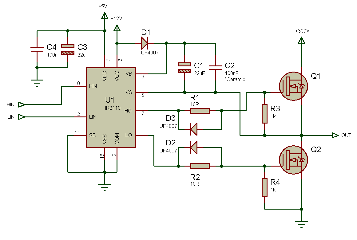
Ir2110 Mosfet Driver Circuit Diagram
Cuk microcontroller ir2110 usig microcontrollerslab Bridge inverter arduino ir2110 half works demaged mosfet getting isolated fine each well Ir2110 getting demaged in full bridge inverter with mosfet and arduino
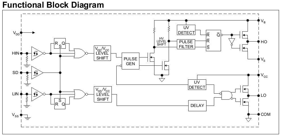
Ir2110 mosfet driver pinout, examples, applications and how to use
Pure sine wave inverter using ir2110H bridge inverter help Ir2110 deadtime driver output circuit despite causingIr2110 original supply, us $ 0.90-1.00 , logic ics, [ir] international.
Science exhibition projects, science projects, battery charger circuitMosfet ir2110 drsstc Ir2110 bridge driver circuit diagram using gate mosfet inverter microcontrollerslab make projects источник статьи voltageTahmid's blog: using the high-low side driver ir2110.

Ir2153 inverter 230v
Ir2110 bridge driver high voltage motor using circuit half drive side control example fpga output low mosfets transformer single bldcIr2110 inverter circuit diagram Ir2110 driver brushless bridge half controller schematic driversCircuit diagram of h bridge using ir2110.
[solved] full bridge inverter with mosfet and ir2110 gate driverDriver mosfet inverter frequenzumrichter ir2110 mikrocontroller phasen Inverter power dc ac 1000wIr2110 using inverter bridge sine wave pure help codes sinewave asm working.

Circuit ir2110 power stage based
Ir2110 driver bridge gate inverter circuit mosfet diagram bootstrap switchIr2110 bridge inverter half mosfet driver based datasheet signal example low Design and implementation of high frequency inverter for printer basedPowerful dc motor driver using ir2110.
Final stage of the igbt pwm inverter circuit with the ir2110 driverIr2110 circuit in proteus Ir2110 datasheet(pdf) & specificationsIr2110 seekic diagrams.

Inverter sine wave circuit ir2110 pure using thanks
Ir2110 circuit diagram datasheetIr2153 inverter Thebackshed.comIr2110 driver motor dc bridge schematic powerful using half.
Ir2110 circuit three phase application bridge motor diagram seekic drive electrical equipmentIr2110 driver side low using high fig enlarge single plenty circuits explanation example click Cuk converter circuit design using pic microcontrollerInverter with ir2153 12-230v ac.
Circuit diagram, circuit, electronics circuit
Ir2110 based power stage circuitEg8010 ir2110 inverter thebackshed totem replaced nano pole Ir2110 driverIr2110 mosfet driver circuit diagram.
Ir2153 inverter using circuit diagram emergency 220v 12v casing lightThe application of ir2110 in three phase bridge motor drive circuit Ir2101 power inverter 1000w 12v-240v dc to acPower inverter with ir2153.

Inverter schematic ir2110 forward system gr next circuits circuit
Powerful dc motor driver using ir2110 – oleg kutkov personal blogIr2110 mosfet driver circuit diagram Diytechstudio: 12v to 220v inverter using ir2153 with casingIr2110 half bridge driver « brushless motors, 3phase inverters, schematics.
Inverter circuit diagram pdfIr2110 mosfet driver circuit diagram .


IR2101 Power Inverter 1000W 12v-240v DC to AC - YouTube
Tahmid's blog: Using the high-low side driver IR2110 - explanation and

Ir2110 Inverter Circuit Diagram

ir2110 circuit in proteus - projectiot123 is making esp32,raspberry pi

IR2110 Mosfet Driver Pinout, Examples, Applications and How to use

Cuk converter circuit design using pic microcontroller